Operation Panel For Lathe
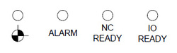 |
LED SIGNAL
1:AXIS ZRN 2:ALARM, LED ON 3:POWER ON, LED ON 4:I/O MOTION CARD SELF HARDWARE TESTING, CONFIRM OK, LED ON |
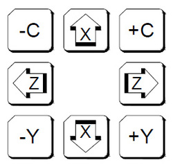 |
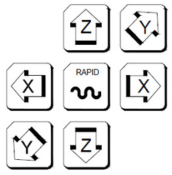
AXIS SELECTION
These buttons are used to command moving axis direction under JOG, RAPID and ZRN modes: 1.For example, pressing X key under JOG mode, it will move to +X direction, and release this key, it will stop moving. Other axis has the same functions 2.Pressing RAPID and X under RAPID mode, X axis will go rapidly to plus direction, release this key and the X axis wil stop. Other axis has the same functions.3.Pressing X under ZRN mode, X axis will go plus direction to return home. Other axis has the same functions. |
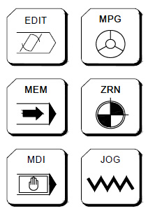 |
MODE SELECT
There are 7 modes on this operation panel, which are:(EDIT)(MEM)(MDI)(MPG)(ZRN)(JOG)(RAPID) Note:RAPID will be introduce at next chapter.(1)EDIT Users can edit new program or modify old one. (2)MEM Users can do auto program executing. (3)MDI Users can execute single block program, modify parameters and setting data (4)MPG Users can use MPG to control the feed of servo axis. All hand wheel control panels provide ratio selection switches, such as 1 ratio, 10 ratios, 100 ratio, and unit means the smallest commanding unit (0.001 mmor 0.0001 inch). Axis direction selection keys are used on control panel. 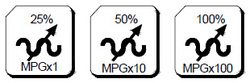 5:ZRN
Operating home return of each axis. When changing to this mode, pressing home return direction button of each axis (the same button as JOG). This axis will start home return procedure according to the setting speed of the parameter until reaching DOG. Also, servo axis starts searching for the home position and it will stop when reaching home point. At this time, this axis +ive direction light will be ON. Also, when users switches to HOME, this light will be ON in order to remind users to define machine to complete HOME RETURN motion. Please do the Home Return procedure before doing other part program every time reboot the machine in order to ensure each coordinate’s accuracy. Meanwhile if customer use servo system with absolute encoder, when you return home you don’t have toreach DOG, you can directly go back to home and complete this procedure.6:JOG Users can move axis by choosing moving direction, but the moving speed is decided by feed speed.JOG Flow:Move axis7:RAPID Under this mode, users can choose axis direction to move axis, moving speed will depend on Rapid %buttons. Under Rapid mode, there are 3 selections for you to choose, G00 when executing workingprogram, RAPID mode and return ZRN’s front section rate. Rapid % buttons has 4 type to select LOW、25%、50%、100%. This speed depends on Parameter 40 to control.RAPID Flow:Move Axis |
 |
SBK
Control single block button, press this button to turn on, and press again to turn off. When single block button is ON, program will be processed by single block, and will not have continuous actions, every single blocks need you to press CYCLE START again and again to operate. |
 |
MPG DRN
Control MPG dry run button, press this button to turn on, and press again to turn off. When system cycle start, MPG can control the operation and change the program coordinate to move with servo axis. When MPG runs faster, the program will be executed faster, but it will be faster then the programfederate command. When MPG stops, the program will stop. |
 |
OP STOP
Control optional stop button, press this button to turn on, and press again to turn off. When program was processed to M01, it will stop, but if users want to continue, users need to press CYCLE START to start again. |
 |
BDT
Control optional skip button, press this button to turn on, and press again to turn off. Those program’s head with this mark ”/”, this line’s program will be skip. |
 |
TRU CW
This is manual turret CW button, under manual mode,(here means JOG、RAPID、MPG), press this button(CW LED ON), turret will rotate CW, until you release this button, turret will stay at next position. This button’s situation will not maintain, in the other words, when you release this button, the function will stop. (Lights will be OFF). |
 |
TRU CCW
This is manual turret CCW button, movement is the same with TRU CW. |
 |
CHIP
Control chip conveyor CCW button, press this button to turn on, until you release this button, the function willstop. |
 |
CK
Spindle chuck button, press this button to control chuck. |
 |
CTCH
Workpiece conveyor button, press this button to control conveyor. |
 |
TB
Tailstock ejector button, press this button to control tailstock ejector. |
 |
BLOW
Control air blow button, press this button to turn on, and press again to turn off. |
 |
W.L
Control working lamp switch, press this button to turn on, and press again to turn off. |
 |
COOL
Control coolant button, press this button to turn on, and press again to turn off. |
 |
F1 、 F2 、 F3
F1、F2、F3:These buttons are for machine makers to define. |
 |
OT REL
OT REL is the short name of Over Travel Release. There is one limit switch at end of each traveling side of servo axis in order to prevent to damage servo structure by colluding. When servo structure reaches traveling limit, over traveling will occur, which implies emergency stop. When the screen has “EMERGENCY STOP OR OVER TRAVEL” and this light is ON, please check whether or not the servo structure is over traveling. If it is over traveling, change the mode to MPG or JOG mode first. Then pressing this light (let this light ON), so the controller will ignore this over traveling emergency situation temporarily. This implies that users can use hand wheel or axis-direction key to move servo axis back to the travel range. Releasing (OT REL) button at this time, in order to let the system to continue travel checking. If everything is working normally, which means “CNC Ready” will replace “CNC Not Ready”, and then continue operating. If other warning messages occur, please press [RESET] button before returning back to normal. Please be careful about moving direction, and moving speed while moving the servo structure in order to prevent collusion. Note: It is possible that over traveling situation occurs when “NOT Ready” condition occurs without anyprediction. Please put the over traveling condition into the checking item when searching for reasons. |
 |
MPG
Controller uses MPG to produce pulse , and use pulse to move position. Users can use MPG mode with axis direction keys and MPG ratio to move axis to target place precisely. Also If users want to use MPG DRN function, users will need to use MPG to control execution directions. MPG CW is to execute program from upto down, and vice versa. User can use this function to test cutting and prevent damage. |
 |
EMG-STOP
Using this butting under the condition of danger or emergency and all motions will stop. To cancel is to turn the button by following the arrow direction. When the button is jump up automatically, the emergency stop is released. When the button is pressed, the system is in “Not Ready” condition (condition column will occur “Not Ready”). In order to reach completed safety, the feed driver power in the power cabinet will be disconnected. Before releasing emergency stop, please ensure whether or not the broken source is excluded. Please executing home return procedure after the emergency stop is released in order to ensure the accuracy of the coordinate position. Note:When you press EMG-STOP, you will need to do return ZRN every time while you release it. Butabsolute encoder is not included in. |
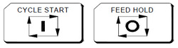 |
CYCLE START & FEED HOLD
CYCLE START After key-in a program, switching the operation mode to MEM or MDI mode and pressing “CYCLE START” button to executing programs. While the program is executed, this light will be ON. The timings of using “CYCLE START” button are the following: 1. Auto executing in MEM mode When a program is selected in MEM mode, pressing “CYCLE START” button to execute the program. The light will remain ON during program executing time until the program execution is finished. Before executing program, the three axes must return home. If not returning back to home, users can switch the “Reference Need to OFF” on the Users Define screen. By doing this, program will be able to execute without returning back to home. 2. Manual executing in MDI mode Users can key-in a block of program commanding such as G91 G01 X100. Z100 in MDI mode, then press “CYCLE START” button to execute this single block command. The intension of this executing mode is different than that of MEM mode, which is always used in testing some motion. The light will remain ONduring executing time until the executing is finished. FEED HOLD Press this button to stop program executing temperately. During the pause time, “FEED HOLD” light will be ON. M, S and T will remain in the current condition. Please press the “CYCLE START” button again in order tocontinue executing the unfinished program. |
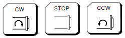 |
Spindle Operation key
Under manual mode(here is JOG、RAPID、MPG), spindle rotation can be controlled by these 3 keys. CW :Rotate in CW direction. STOP :Stop rotating CCW :Rotate in CCW direction. Under Manual mode, the rotation speed command is 0% ~ 120% at CW or CCW. If users want to switch CWand CCW, they need to do STOP first. |
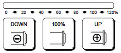 |
Spindle speed turn key
When spindle is under MEM or manual mode, user can use M3(or M4)Sxx…..to turn on spindle. Rotation speed of spindle can be tuned by UP+、DOWN- and 0% ~ 120%. For example, give command of M3 S1000, turn key is at 120%, exact rotation speed is 1200PRM.If at 10% 100PRM, press 100% key to return back to 1000PRM. |
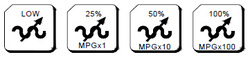 |
Feedrate turn key
These are the turn key of ratio speed for G00, RAPID and ZRN. There are 4 sections of speed, LOW、25%、50% and 100%. LOW speed will be determined by Pr.40. |
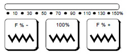 |
JOG turn key
FEEDRATE: Under MEM or MDI mode, use G01…F… command to move servo axes. Its exact federate can be tuned by this turn key from 0% to 150%. For example, F100=100mm/min, but if changing turn key to be 50%, its exact federate is 50mm/min. At most machines, this turn key is effective to JOG mode. For example, current setting is 10%, 10mm/min and press 100%, the exact federate will be changed to100mm/min. |
Operation Panel For Milling Machine
 |
AXIS SELECTION
There are 7 modes on this operation panel, which are:(EDIT)(MEM)(MDI)(MPG)(ZRN)(JOG)(RAPID)Note:RAPID will be introduce at next chapter. (1)EDIT Users can edit new program or modify old one. (2)MEM Users can do auto program executing. (3)MDI Users can execute single block program, modify parameters and setting data. (4)MPG Users can use MPG to control the feed of servo axis. All hand wheel control panels provide ratio selection switches,such as 1 ratio, 10 ratios, 100 ratio, and unit means the smallest commanding unit (0.001 mm or 0.0001 inch). Axis direction selection keys are used on control panel. |
 |
MST
MST, press this button to let MST ignore function ON, press again to release this function.Part program with ” M ” ” S ” ” T ” code will be ignored and will not be executed. |
 |
MAG CW
This is manual magazine CW button, under manual mode,(here means JOG、RAPID、MPG), press this button(CW LED ON), magazine will rotate CW, until you release this button, magazine will stay at next position. This button’s situation willnot maintain, in the other words, when you release this button, the function will stop. (Lights will be OFF) |
 |
MAG CCW
This is manual magazine CCW button, movement is the same with MAG CW. |
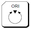 |
ORI
Press this button to do orientation, press reset to release this function. |
 |
CHIP CW
Control chip conveyor CW button, press this button to turn on, until you release this button, the function will stop. |
 |
CHIP CCW
Control chip conveyor CCW button, press this button to turn on, until you release this button, the function will stop. |
|
|
|


